
Blog: posted by Steve Hosein, March 15, 2018
Designing a Dobson (Newtonian Reflector) Telescope for Optimal Performance
If you landed on this article via Sky & Telescope magazine's August 2018 issue (available late June), welcome! Thank you for your interest in this project. If you arrived here via my blog, be aware that no "business" topics will be covered in this article; however, it is a good example of why I am well-suited to (and enjoy working with) science and engineering customers.

Design Goals(Skip down to image gallery)
I chose to optimize for visual observing rather than astrophotography out of preference, but also I think this approach makes the most sense for a non-motorized Dobson.
Maximize sensitivity and contrast: I want to see faint DSO’s and dark skies are getting harder to find
Increase light throughput and minimize light obstructions
- increase the fully illuminated field from essentially zero to ~9 mm by adding shorter focuser (Feathertouch), shortening the lightpath from the secondary to the focal plane and lengthening the lightpath from the primary to the secondary thus ensuring that the secondary is better able to reflect the narrower cone of light towards the eyepiece.
- secondary is held in place with three vanes separated by 120 degrees each. Each vane is a doublet of 0.008” diameter guitar string. Six guitar tuning pegs are used to position the secondary (and to collimate).
- a new secondary holder that slightly reduces central obstruction
Reduce stray light in OTA
- thin baffles were added from the front of the OTA to the primary-mirror-side of the focuser. Simple perpendicular baffles beyond this point could actually diminish performance by increasing stray light.
- Inside of OTA painted with “scenic black”, a flat black paint formulated for the film industry. There is a large film industry presence in Vancouver. The spider and the sides of secondary mirror were also painted.
Reduce effects of boundary layer(s): I don’t want to view planets “through flowing water”
"Ventilate” the OTA around the primary mirror to allow more airflow and faster heat transfer
- holes 1.75” in diameter were drilled around the OTA extending above and beneath the primary mirror
- to ensure rigidity of a perforated OTA, the sonotube was reinforced by sliding it into a PVC drain pipe
- a light shield “jacket” was placed around the outside of the OTA in this region, leaving about a 0.8” airgap between the outside of the OTA and the wood veneer “jacket”. The wood veneer tended to split so I replaced it with a plastic sleeve.
Secondary holder should have as little thermal mass as possible
- spider vanes are fine guitar strings rather than sheet metal slats - should reduce any small boundary layer around the vanes
- holder is simple and light: a bolt, two nuts, a machined aluminum sleeve, and a short, wooden dowel cut on a 45.
Performance Evaluation
Caveat - It is impossible to make definitive, quantitative statements regarding improvements without a proper negative control. The negative control would be a near duplicate of this telescope, less the one feature (baffles, or guitar-string-vanes, or ventilation holes) being evaluated at the time. Comparative observations of the exact same celestial body through both scopes under identical conditions would be required. It’s not feasible for a self-funded amateur with a day job! So I will limit myself to qualitative statements.
Positioning the secondary can be done while looking through the focuser – simply twist the “tuning pegs” as you look at the mirrors/reflections. No need to move back & forth, sticking a screw driver in the spider to adjust anything
Alignment of secondary easier on eyes. - one unforeseen benefit is that if using a laser to align the secondary, you can easily see if the red dot is on the centre of the primary by looking through a ventilation hole. It is much easier on the eyes than looking down the OTA and having the harsh laser reflected nearly directly into your eyes. Although looking through a ventilation hole provides an off-axis view, there is no issue of parallax because the red dot would be literally on the centre mark of the primary (not aligned above it).
The cooldown period appeared shorter; it’s very easy to remove the veneer “jacket” (it has a Velcro strip closure) and let the cool air access the mirror more easily. Once the jacket was put back on and observing began, few effects were apparent. For transient effects, it is not easy to distinguish between disturbances in the atmosphere and boundary layer on the mirror, but this was better than my purchased Skywatcher 8” Dobson.
Glare reduction was impressive – observing from a 6 story rooftop in highly-light-polluted downtown Vancouver, with the scope directed at Jupiter over a brightly-lit skylight only 10 feet away, I was amazed at how well the scope performed. But Jupiter is a bright target (filters were required to reduce Jupiters light). Next, I turned the scope to the Great Nebula in Orion, and after that to Andromeda. I was very pleased with the view of the nebula and the galaxy given the conditions; with all the light pollution, I could barely see a constellation with which to start star-hopping.
Dobson Mount and counterweight
When designing the mount, I wanted a super smooth action. I found my SkyWatcher to move smoothly once you set it in motion, but starting that movement to track an object could be jerky, leading to overshooting the target and having to move back. (Basically, I wanted an improved coefficient of static friction for both axes.) Thus, rather than using teflon sliders, I used bearings. The altitude axis relies on four roller bearings (two on each side). The azimuth axis benefits from a "lazy Susan" bearing.
This design worked extremely well ... in fact, almost too well. I had to add three nylon bolts to the platform to add a controlled amount of friction (azimuth). Not only did this allow me to add as little or as much friction as I want, it also stablilized the platform: the lazy Susan bearing had a little play in it which this rectified.
For the altitude, I realized that a counter-weight system would be best. Anything that adds friction negates the smooth action of the roller bearings. A counter-weight allows you to keep the slippery action but the scope stays put once you take your hand off.
Gallery
NB - I apologize for the poor quality of the photos in the gallery below. I took them quickly on my cellphone as a personal record; sharing them had not crossed my mind until I was nearly finished the project. Some have required touching-up with software just so you can make out certain features. This too was rather "quick and dirty" but hopefully it's enough.
Starting Point
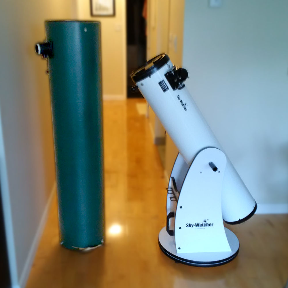
This was my new project: a decrepit old OTA that housed an interesting primary mirror. Beside it, the SkyWatcher 8" that I had bought a few months previously. Like many of their customers, I spent hours talking to Harout and Bryce about collimation and other such topics. Bryce lent me Vic Menard's guide on the subject. Finally, given my interest in technical aspects of the hobby, Harout proposed that I buy this old OTA and start a "project".
Old Spider and Vanes

This is a view down the old OTA (primary mirror removed)
Old focuser
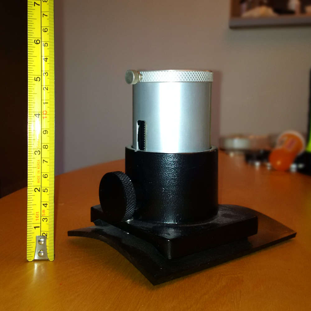
This was the original focuser which was quite tall. I purchased a new Feathertouch so that it would be shorter thus allowing me to reduce the distance between the focal plane and the secondary mirror which in turn would allow me to lengthen the distance between the primary and the secondary such that either a smaller flat can be used or the fully illuminated field increases (or a combination of both). I used the same size flat but increased the fully illuminated field from essentially zero to ~9 mm.
The primary mirror
This was the reason for purchasing the old OTA. This 10" primary mirror is quite thick. It was hand-figured to a 55.5" focal length. The mirror mount also appears to be quite robust and I used it in my new scope. (This photo was taken with flash; notice that an image of the mirror was projected onto the wall behind it.)
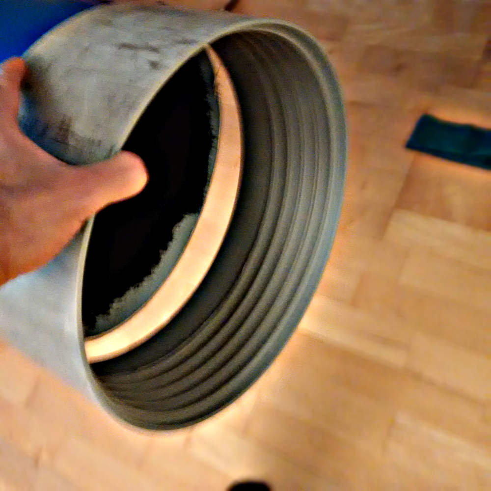
PVC Drain pipe to Reinforce OTA
I purchased a length of PVC drain pipe and had them plastic weld two lathed PVC blocks, one on each side. The two blocks act as a gimble that serves as the altitudinal axis. I do not have a lathe, nor could I have plastic welded the blocks on ... not to mention getting things "square" on a tube. The PVC drain pipe is to add some rigidity to the OTA which is critical for maintaining collimation. (In later steps, I will drill holes in the OTA which will weaken it)
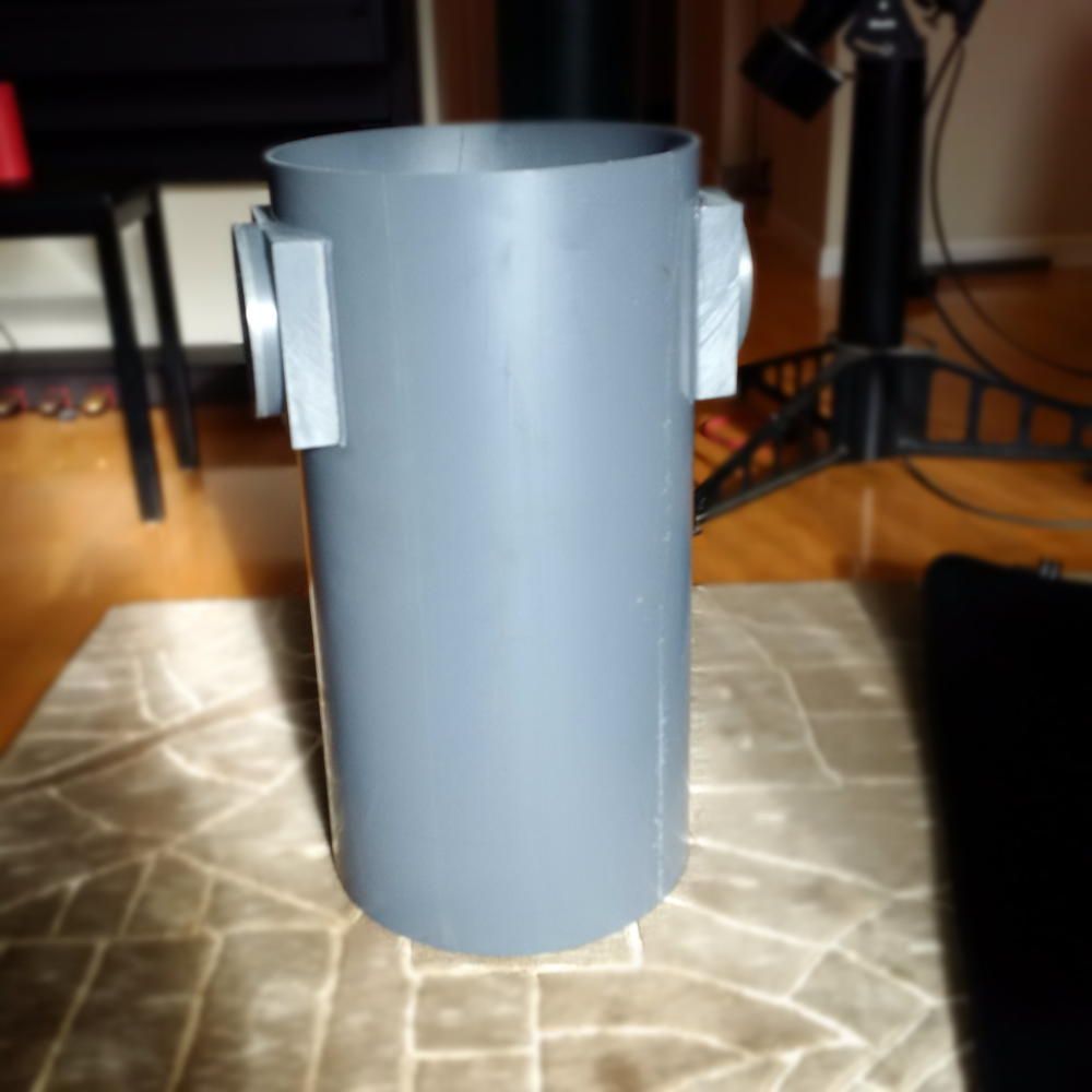
Painted Sonotube in the PVC Pipe
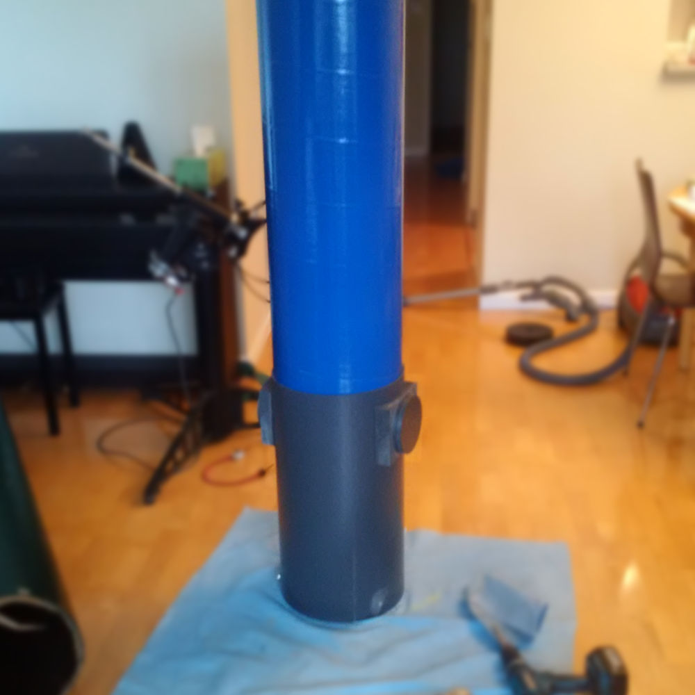
There is a very snug fit between the Sonotube and the PVC drain pipe
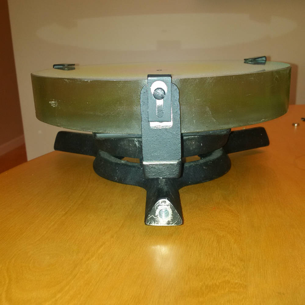
Drilled holes in OTA
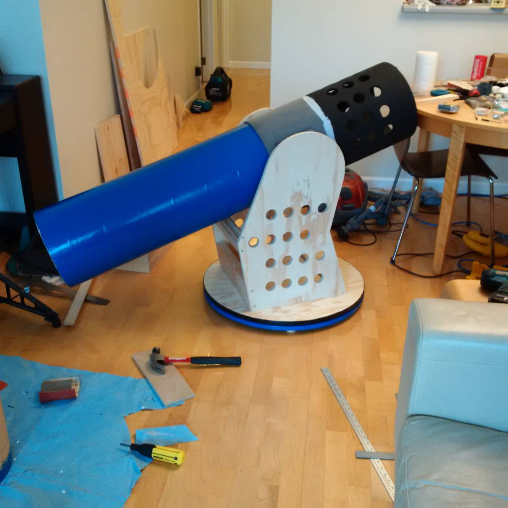
Using a hole saw in a hand drill, I drilled evenly spaced holes around the OTA at the end where the primary mirror would be mounted. Then I painted with primer (Zinsser Bull's Eye 1-2-3). The old Meade equatorial mount made a handy painting jig.
Two Rings to Support Light Shield
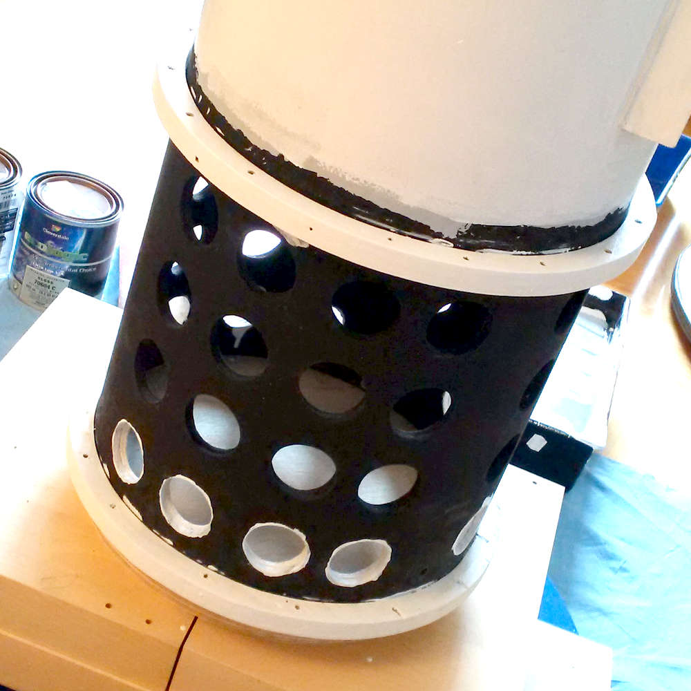
Using a jigsaw and a DIY jig made of a piece of sheet metal and a screw, I cut circles in 3/4" plywood to generate two rings. These rings fit snugly around the OTA and were screwed in place. They allow about a 3/4" air gap between the OTA and the light shield that will be wrapped around it to block light from entering via the perforations. When the shield is on, the air gap allows better air flow. Notice that I also drilled small holes in the rings themselves to allow airflow between air gap and the "exterior".
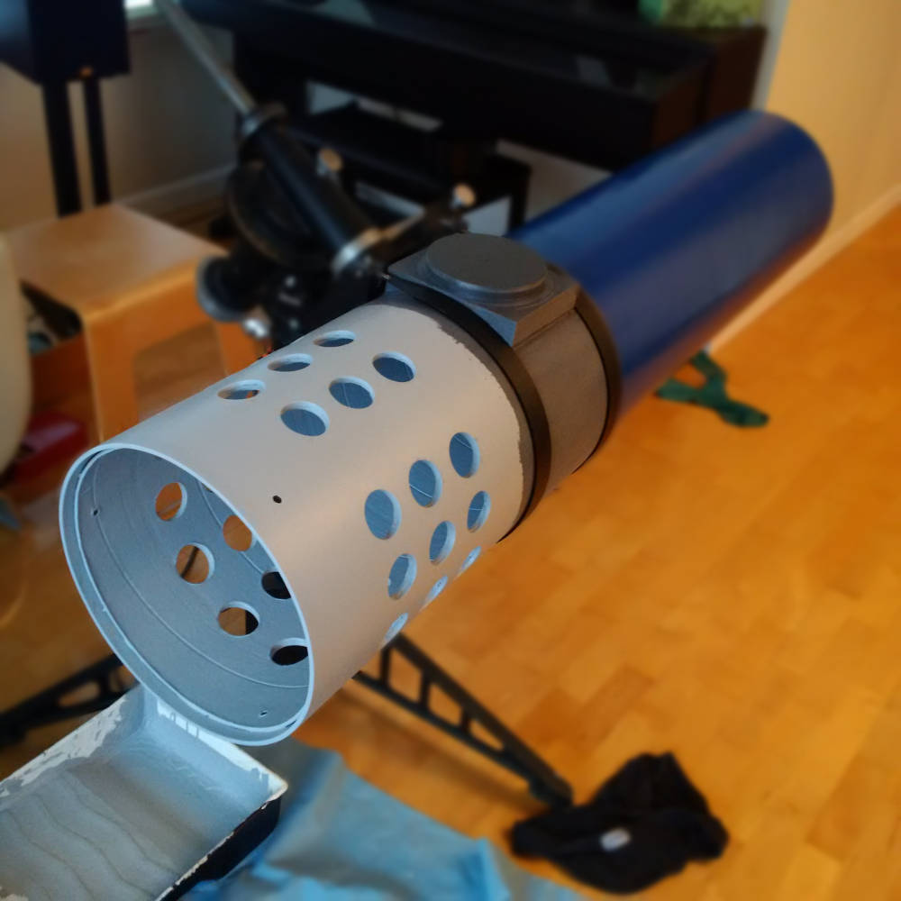
Light Shield
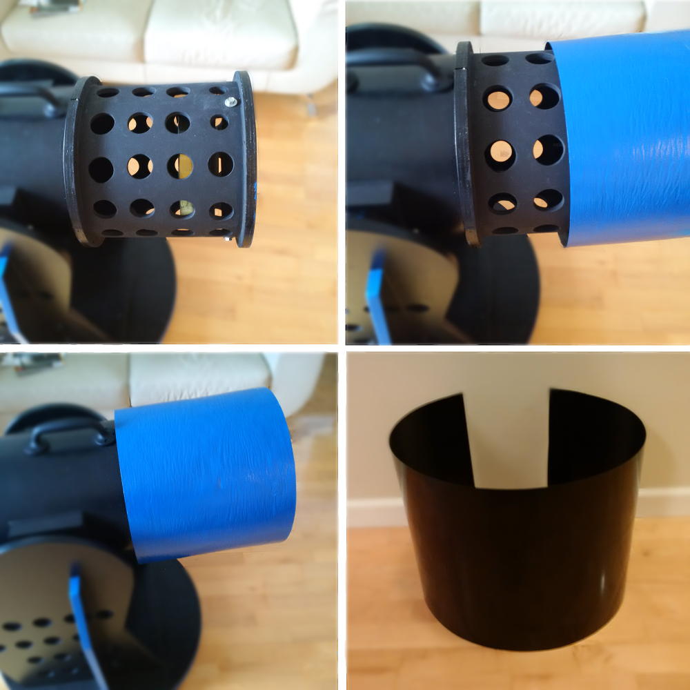
The first shield (blue) looked great but splintered quite easily. I made it out of a sheet of wood veneer. I replaced it with a sheet of plastic ... some sort of construction waste, possibly ABS (bottom right corner). Both designs were a "wrap" that closed via a Velcro strip at each end. The image on the top left shows that the perforations extend above and below the primary mirror.
Baffled Ring (PVC)
A ring was added to the end of the Sonotube to help maintain the circular form of the OTA at the front aperture. This ring was a section of thicker-walled PVC drain pipe. I had wide grooves cut in with a lathe so as to create baffles. Afterwards, I scribed two circular baffles (not shown here) out of a thin sheet of black ABS using a box cutter. Then I epoxied one to each end of the ring. The one on the interior side just resulted in one extra plastic baffle (before the metals baffles start). The one on the exterior side serves as the entrance pupil.
Metal Baffles
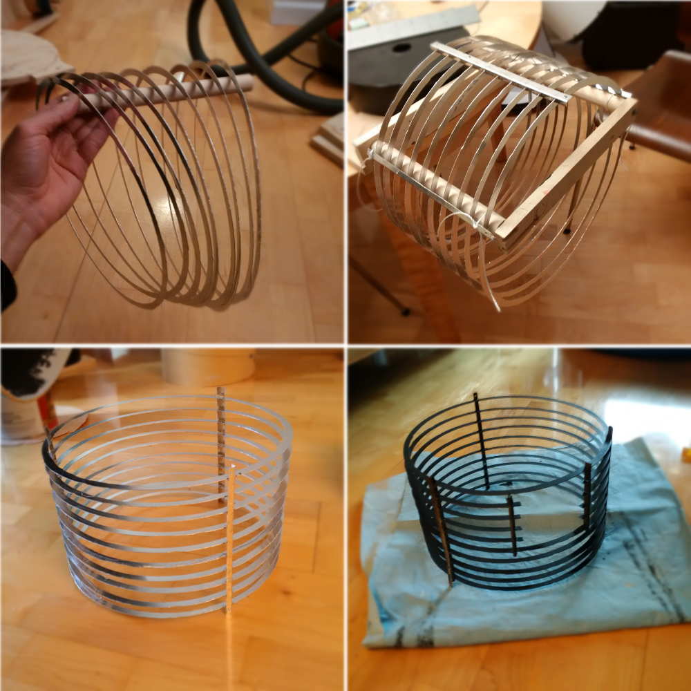
Using a Dremel tool and a scribe, I cut circles out of sheet aluminum. This was a painful process as the scribe was not reliable enough and the Dremel bites into the metal at times The top left shows the circles; top right the circles are aligned on the jig for gluing (used epoxy as well as perpendicular side braces with tabs and slots); bottom left, the baffle cage; bottom right, the primered baffle cage with a hole cut out for the focuser draw tube.
Versions of Secondary Holders
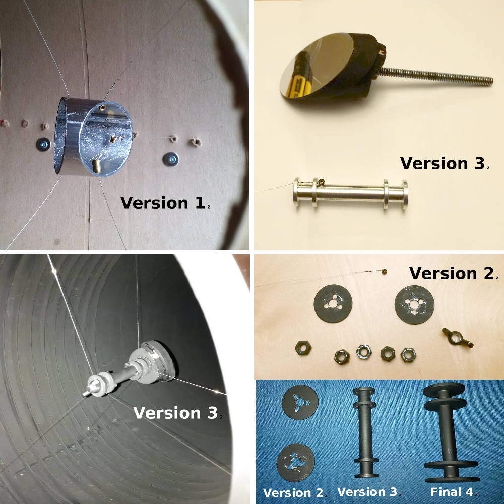
Version 1 (top left) was abandoned quickly. It was a minimalist design with good points of attachment for the strings but it was missing a rotational axis. I thought I could get away without the rotation, but relying solely on manipulating the six wires (via tuning pegs) proved too challenging. Version 2 performed well and I used the scope like this at first. But because it relied on nuts and washers, there was sometimes slippage as the wires were tightened so positioning the secondary was problematic. Version 3 was a single piece of aluminum turned on a lathe. Although it had a similar diameter to version 2, it has increased torsional vibration. I believe the "play" allowed by the slipping washers in version 2 dampened those vibrations At the suggestion of Jerry Oltion, I made a final version with a larger diameter (bottom right corner). Notice on the final version (4) that the top flanges have a slightly smaller diameter than the bottom two flanges. The larger flanges go right up against the secondary mirror and the smaller ones face the entrance. This was to allow for the largest diameter (to reduce torsional vibration) while ensuring that the holder stays well within the "shadow" of the secondary mirror itself.
Baffled Aperture with Secondary

Here you can see the completed, painted baffles. In the photo, I am just installing version 2 of my secondary. You can see the guitar strings as well as the gold-coloured tuning pegs in the black housings on the exterior of the OTA. Also, the first (closest) ABS baffle that serves as the entrance pupil is plainly seen. The paint used inside the OTA is called "Scenic Black" and is specially formulated for the film industry by Cloverdale Paint. They use it on set to prevent light reflections etc. I think it does the trick.
Secondary Installed (Final Version)
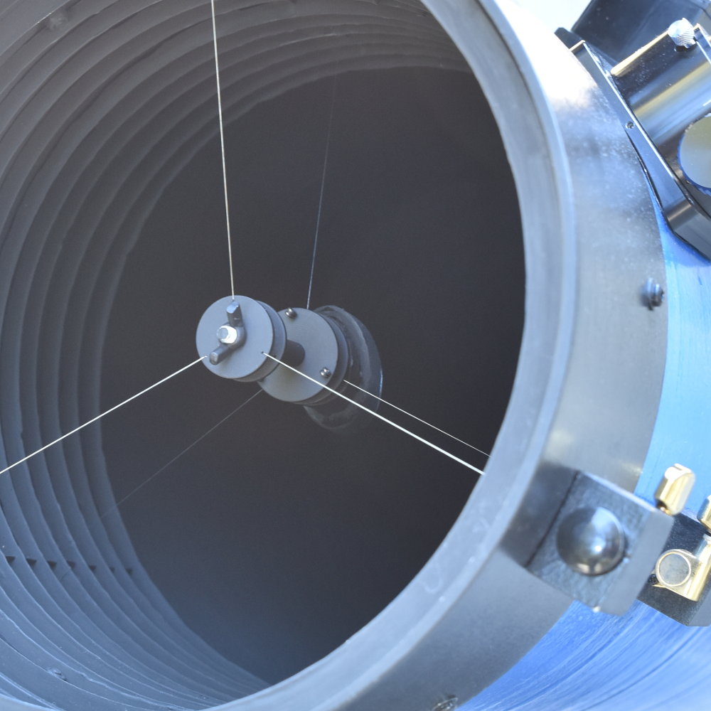
This is the final version of the secondary, installed.
Dobson Mount
The Dobson mount was made with 3/4" plywood. I used a "lazy Susan" bearing for the azimuthal axis. I used 4 roller bearings (two on each side) to support the PVC gimble on the OTA; this served as the altitudinal axis. I had been frustrated with the teflon sliders used on my Skywatcher; when you want to nudge the scope to track an object, you feel resistance and then a sudden release and you can go too far. I wanted my mount to be slippery smooth. Both axes are. in fact, I had to add a three nylon bolts to the platform so that I can add more friction in a controlled manner (azimuth). The altitude was a dream to move ... however, it wouldn't stay put! I realized I needed a really practical counter-weight system.
Counter-weight System
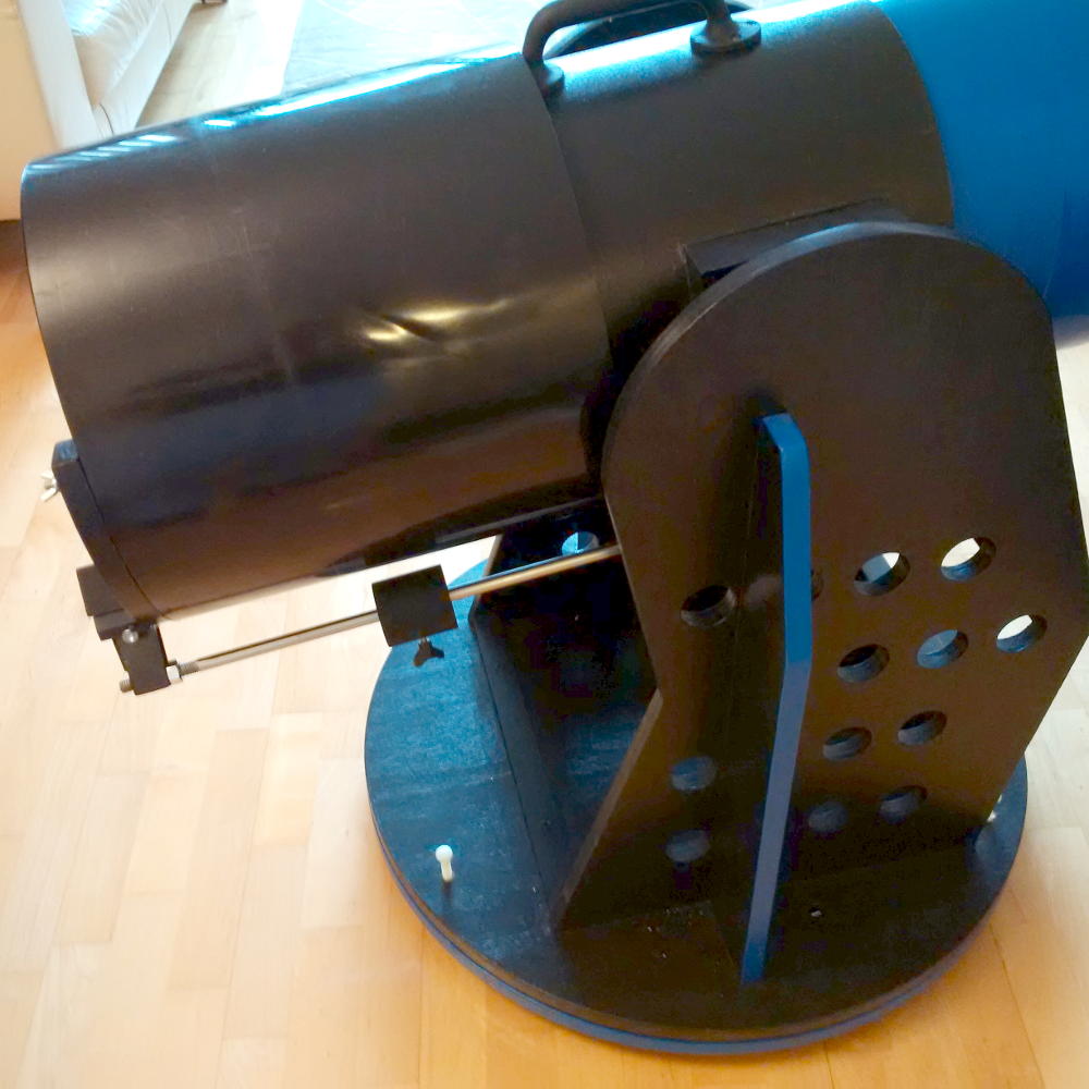
I wanted one simple weight that could slide along as needed. I hack-sawed off the loops of two finder bracket mounts and smoothed the remaining piece with a file, and drilled some holes. I bought a steel rod and had it threaded at each end. I bolted two furbs to the scope, one on the OTA and one on the panel that cover the end of the OTA (behind the primary). The result was just what I was after. It looks good and it's perfectly functional. Importantly, thanks to the furbs, it comes off the OTA for transport.
Finally finished
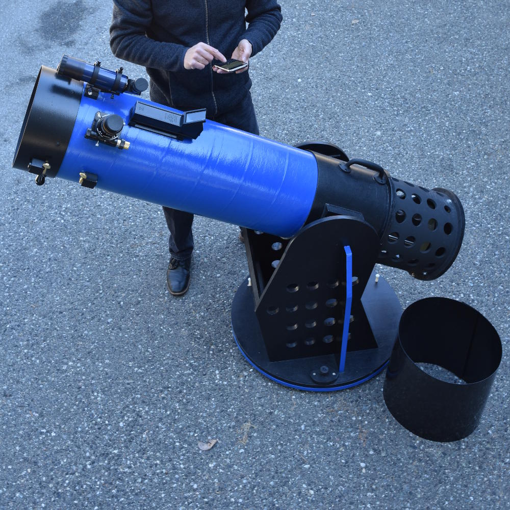
Now all I need is clear skies!
Downtown Vancouver Stray light Test
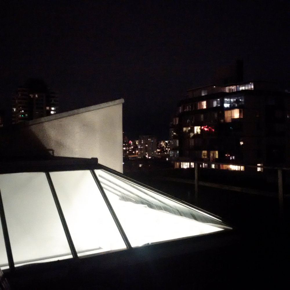
A large, bright, skylight spews out light pollution as do the lights from nearby buildings. This photo was taken from the position of the telescope, looking towards the south east where Jupiter was (a little out of frame on the top-side of the photo, dead-centre). I observed both Jupiter and the Great Nebula in Orion and was happily surprised with the views given the amount of stray light present.
Acknowledgements
I'd like to thank Harout Markarian and Bryce Tordiffe of Markarian Fine Optics. Harout sold me a hand-figured 10" diameter primary mirror and followed up with endless encouragement and enthusiasm. Bryce lent me books on amateur telescope making (and occasionally even tools) and was a wealth of DIY information. I am grateful for their knowledge, support and friendship. I'd also like to thank Jerry Oltion for accepting to write about this telescope in his Astronomer's Workbench column and for his advice on making my secondary holder with a larger diameter to reduce torsional vibration.